
Pas Loudness Kit
How To Build
Overview
After many requests, we have released this simple but effective loudness function/kit suitable for our Dynaco PAS upgrade kits.
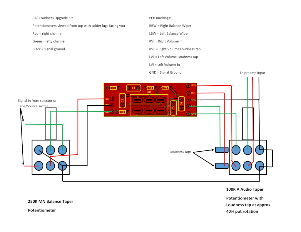
Please note, this loudness function is designed to be used with a 250K Balance, 100K Volume controls and our PAS Preamp designs. The 100K volume control MUST have the loudness taps included. These should be at around 40% of the Potentiometer rotation.
PCB Assembly
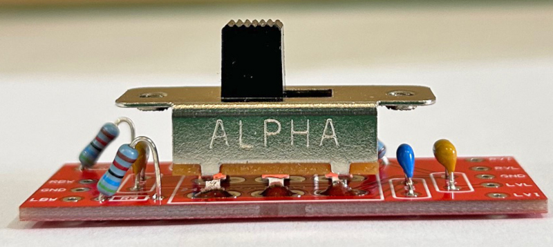
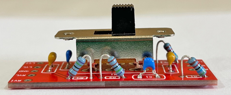
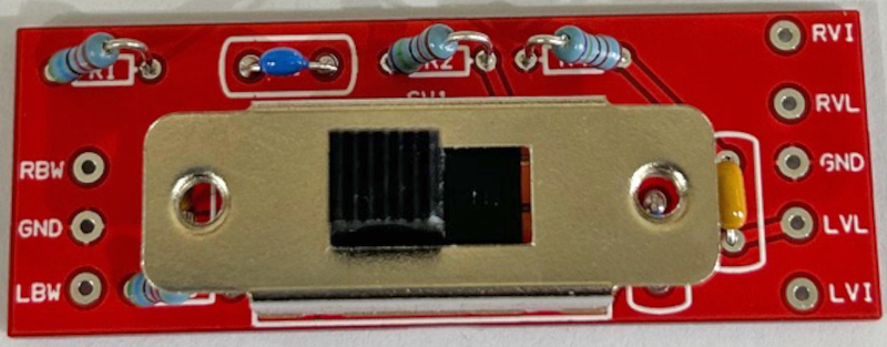
Start with the small capacitors, followed by the resistors, which are installed upright and finally the switch.
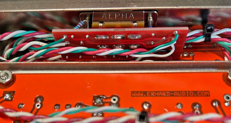
Please note, the switch MUST be ‘lifted’ off the PCB as shown on the photos, otherwise the small metal tabs of the switch assembly will short against the solder pads.
Confirm twice, solder once, see photos of assembled kit and basic solder guidelines below.
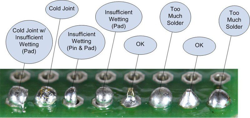
Basic Soldering Guidelines
Loudness Kit Side
Loudness Kit Other Side
Loudness Kit Top
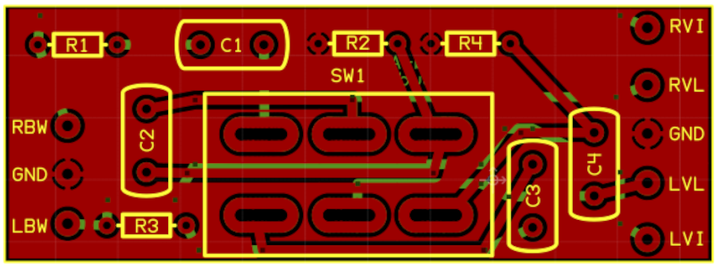
Loudness Kit PCB
Chassis Installation
Screw the loudness assembly into the chassis using 4-40 machine screws, the photo below.
Orientation of the assembly is critical, so that the loudness In/Out switch location coincides with the lettering on the front panel.
Once installed, carry out the wiring detailed next.
Loudness Wiring PCB
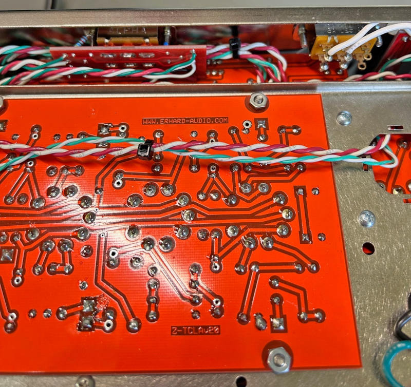
Loudness Wiring Chassis
The above photos show the installation in our PAS NGCT next gen Preamp kit.
Wiring
The loudness function is installed ‘between’ the balance and volume controls, see wiring diagram below.
It may look a bit confusing at first, but take your time looking at the wiring diagram, it is actually pretty straight forward.
Try and keep all wires between the balance, volume controls and loudness PCB twisted and as short as practically possible.
Signal Wiring Loudness PCB
General signal wiring, you will need to modify it by adding the loudness pcb as shown in the previous page.
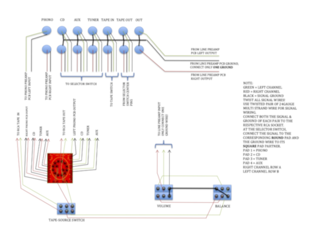
Signal Wiring Loudness General